Increase capacity in your column with a tray design revamp
As shown in Figure 2.1 with a tray column, the feedstock mixture is typically introduced close to the middle of distillation column, to a tray generally recognized as feed tray. The feed tray divides the column into the enriching or rectifying section with all of the trays above the feed tray, and the stripping part with all the trays beneath the feed tray. Depending on the feed condition, the feed enters the feed tray and splits right into a vapour stream and a liquid stream, adding to incoming vapour move and liquid move on the tray. The vapour generated within the reboiler flows up into the bottom tray, and finally exits the highest of the column. It is then cooled by the condenser to liquid once more, and the overhead liquid is held in a holding vessel often known as overhead drum. The overhead liquid is break up into two streams, one recycled again to the top of the column as reflux, and the other removed from the column known as the distillate or top product.
Operating at Partial Reflux
The effects of the operation circumstances, sometimes characterised by hydrodynamic phrases corresponding to froth peak, flooding, and stress drop, are essential features for distillation column design, operation performance, and column effectivity. When trying to extend column capability beyond design rates, an operator may discover loss in separation efficiency or excessive stress drop, indicative of either vapor part or liquid part hydraulic limitations. Jet flooding, also known as entrainment flooding, is caused by massive entrainment of liquid to the tray above. As the tray loading increases, a two-phase mixture of spray or froth begins to occupy more and more of the clear vapor area between the trays. At very high vapor rates, the mixture fills up the entire tray spacing, causing entrainment of significant quantities of liquid to the tray above. Entrainment additionally recycles liquid upward, increasing tray weir masses, froth height, and downcomer loads.
Explore a wide selection of dependable water trucks for sale.
We assume that the condenser is a total condenser and that the reboiler is whole reboiler. Compared to random packings, structured packed towers supply more floor space and have a lower pressure drop. Structured packing could be manufactured from corrugated sheets of perforated embossed steel, plastic (including PTFE), or wire gauze. The result is a really open honeycomb construction with vertical circulate channels giving a relatively high floor space to volume but with a very low resistance to flow.
 Una vez se sumaron todas las placas de acero, se procede a su revisión para garantizar que no haya fuga o rasguño alguno. Finalmente se procederá a colocar las chapas de la cubierta, de tal modo que se evite el acceso a animales o suciedad que deterioren el H2O contenida en el depósito agua potable. Además de esto, frecuentemente será requerida la ventilación del contenido del agua depósito, con lo que muchas de estas chapas dispondrán de orificios destacables a fin de que pueda ingresar aire filtrado sin que entre mugre alguna. Nuestros depósitos de agua están en especial diseñados para solucionar necesidades de almacenamiento de agua de riego. Opción con chapa galvanizada y prelacada en verde, exigida comunmente para depósitos ubicados en espacios naturales protegidos, según la normativa ambiental como prevención de impactos visuales sobre el paisaje. Una vez comentado el proceso de fabricación de los depósitos de agua potable Ilurco, continuamos a destacar las mayores ventajas que estos nos presentan.
Depósitos metálicos con techo metálico
Su adaptabilidad y sus funciones de riego y agua potable, los transforman en tanques depositarios de la más alta calidad. Disponemos modelos en diferentes tamaños, desde los 1000 litros hasta los litros, e incluso aún mucho más grandes. Cualquier proyecto necesario lograras ser llevado a cabo por nosotros dada nuestra experiencia en el sector de los depósitos de agua. Estos depósitos de agua apra riegos dejan un ingreso mucho más rápido que si se contara únicamente con la primordial fuente de suministro del agua.
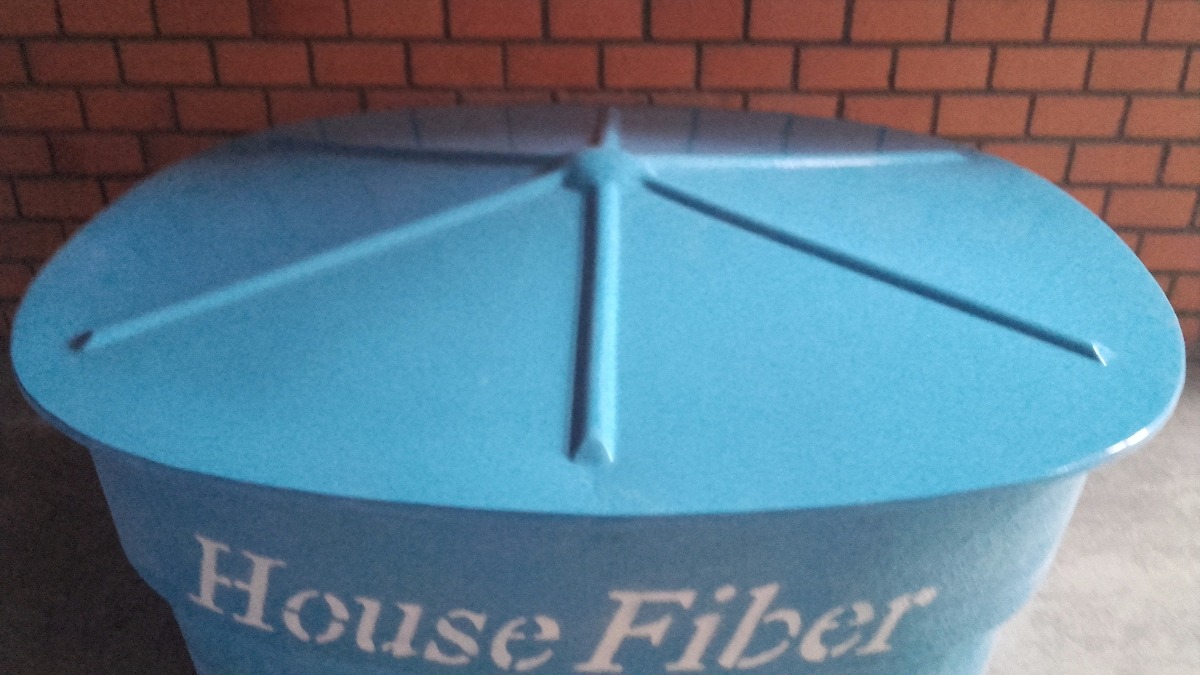
Depositos agua de poliéster. Cuba para transporte y riego de agua 4.000 lts
Se aconseja realizar inspecciones periódicas para advertir y corregir probables problemas de corrosión, asegurarse de que la impermeabilización está intacta, y contrastar el buen estado de todos y cada uno de los complementos. Además, es esencial mantener limpias las superficies internas y ajenas del depósito para impedir la acumulación de sedimentos y algas. Merced a este departamento se consiguió, por poner un ejemplo, la creación de depósitos que posibilitan el almacenamiento de otro tipo de productos no comentados previamente, como puede ser el biodiesel y el biogás. Como hemos señalado antes, ILURCO cuenta con un departamento de I+caixa d água metalica preçO que se encarga del avance de un depósito agua 1000 litro, dando permiso el perfeccionamiento y avance en esta área. Debido al ingrediente P.V.C y la resina Epoxi Blanca se asegura la pulcritud de las aguas, además de permitir una simple limpieza de estas.


